Tolerance Table In Inch

Running and Sliding Limits and Fits For Cylindrical Parts (ANSI B4.1-1967,R1987) All limits shown in chart below are in thousandths of an inches. Symbols H5,g5, etc. Are Shaft and Hole designations used in American-British-Canadian System (ABC). Limits for Shaft and Hole are applied algebraically to the Nominal (basic) size to obtain the. Table 6 - General Tolerances on Symmetry Table 7 - General Tolerances on Circular Run-Out Ranges of nominal lengths in mm Tolerance Class H K L up to 10 0.5 0.6 0.6 above 10 to 30 0.5 0.6 1.0 above 30 to 100 0.5 0.8 1.5 above 100 to 300 0.5 1.0 2.0 Ranges of nominal lengths in mm Tolerance Class H. The tolerance symbols that we use are in line with ISO 492 and ISO 199 and are explained in the previously mentioned tolerance tables and in table 12. The symbols normally refer to dimensional tolerances, only Kia, Kea, Sd, SD, Sia and Sea refer to geometrical tolerances.

We strive to bring to market high-quality, value-packed products. And we’re so confident in our 27-inch 2K monitors that we include a zero-tolerance dead pixel policy — the best in the market. Whereas other monitors for gaming require a cluster of 5 or more dead pixels, we’ll honor a replacement if you just see one single dead pixel. If the 0.12-inch wide channel is machined to 0.11 inches (the low tolerance side for the part), this further compounds the issue. Taking all three of these worst-case values under consideration, it is clear that the set screw will be 0.015 inches too far in one direction and will therefore not fit in the channel.
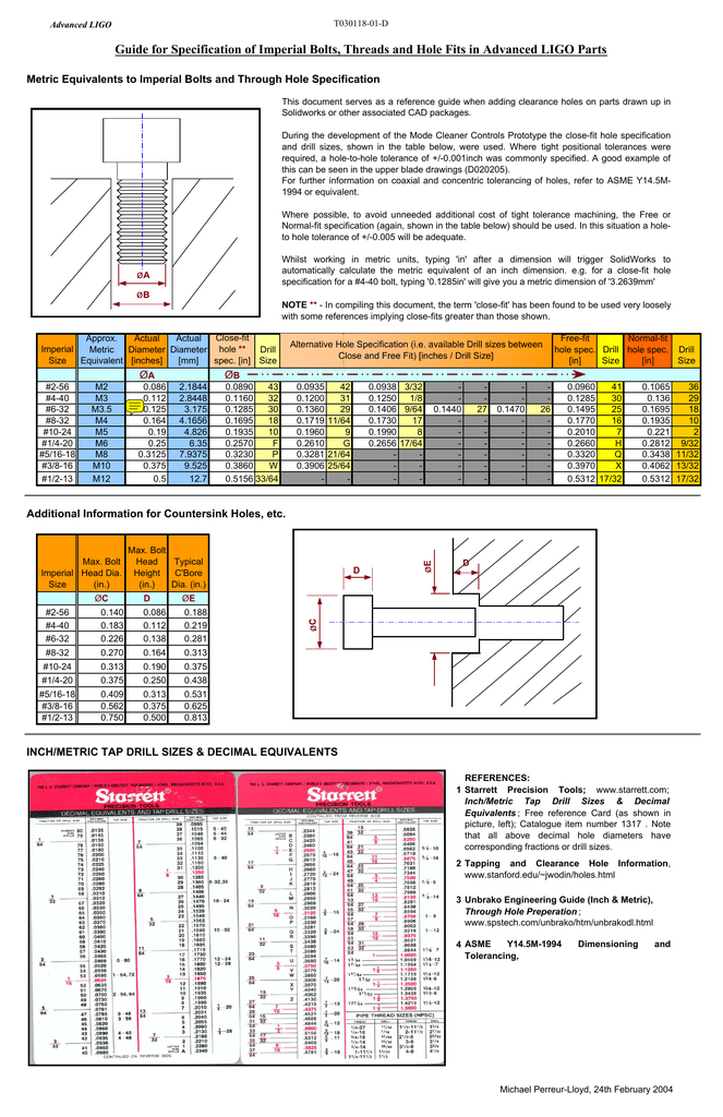
Table

Plain washers are made of ferrous or non-ferrous metal, plastic or other material as specified. The tolerances indicated in the tables are intended for metal washers only.
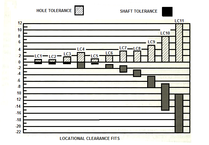
Tolerance Table In Inch

American National Standard Type A Plain Washers - Preferred Sizes ANSI/ASME B18.22.1-1965 (R1998)
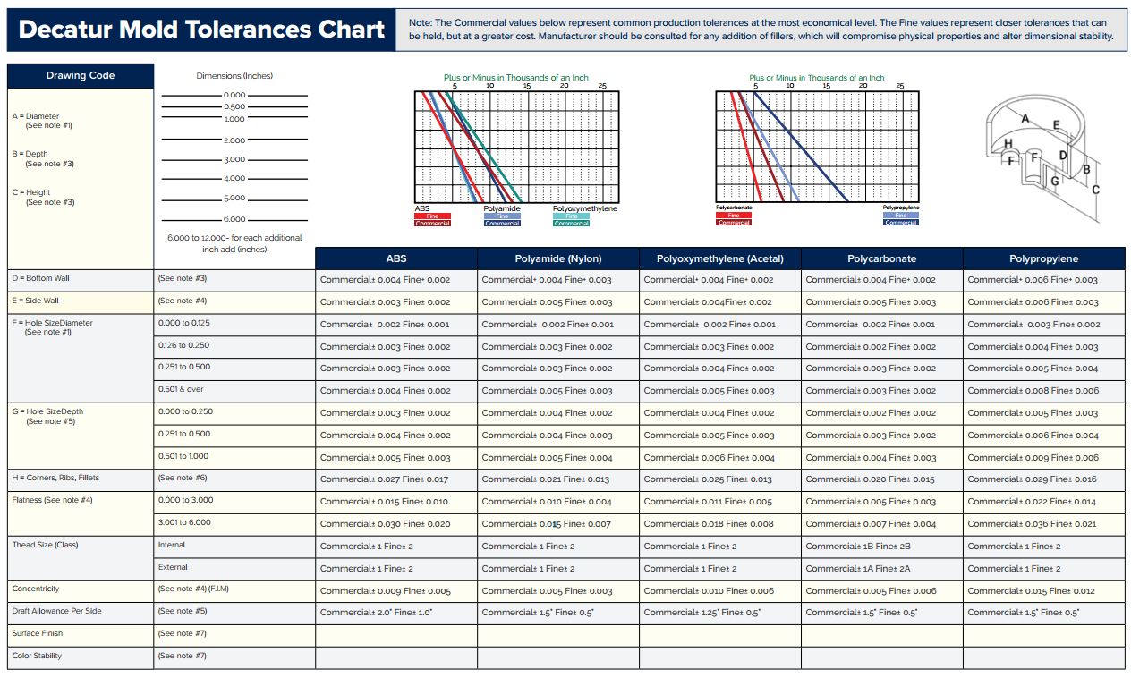
Tolerance Table In Inch

a Nominal washer sizes are intended for use with comparable nominal screw or bolt sizes.
b the 0.734-inch, 1.156-inch, and 1.469-inch outside diameters avoid washers which could be used in coin operated devices.
All dimensions are in inches.
Designation 'N' (narrow) and the Standard Plate 'W' (wide), these sizes as well as all other sizes of Type A Plain Washers are generally specified by ID, OD, and Thickness dimensions.
Location Tolerances: Inside and outside diameters shall be concentric to within the specified inside diameter tolerance.
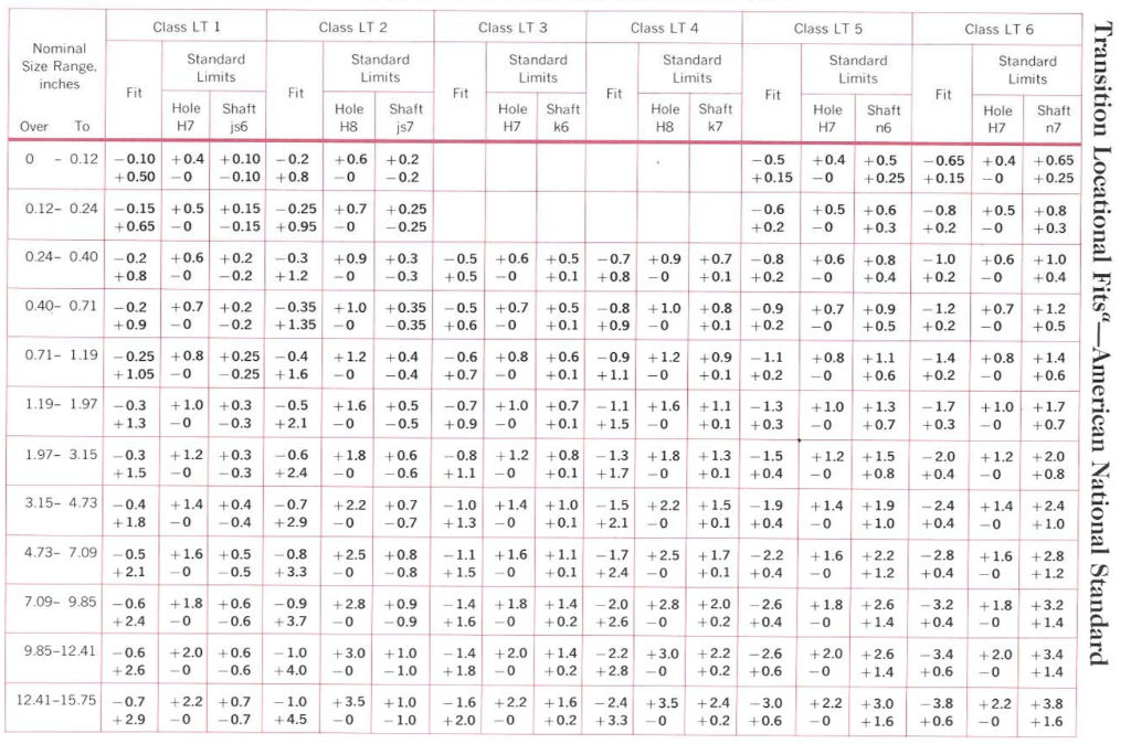
Inch

Tolerance Table In Inch Conversion

© Copyright 2000 - 2021, by Engineers Edge, LLC www.engineersedge.com
All rights reserved
Disclaimer | Feedback
Advertising | Contact | Privacy Policy

Tolerance Table In Inch Cm

Date/Time:
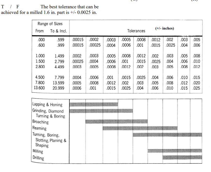
Table

Tolerance Table In Inches

General ISO Geometrical Tolerances Per. ISO 2768

The following are general geometrical tolerances per. ISO 2768 for the following:

  • Linear Dimensions
  • External Radius and Chamfer Heights
  • Straightness and Flatness
  • Perpendicularity
  • Symmetry
  • Runout

Related Mechanical Tolerance Design Data

Variations on dimensions without tolerance values are according to ' ISO 2768'. All tolerance limits are given in mm.

ISO 2768 and derivative geometrical tolerance standards are intendedto simplify drawing specifications for mechanical tolerances. ISO 2768 is mainly for parts that are manufactured by way of machining or removal of materials.

Linear Dimensions:

Permissible deviations in mm for ranges in nominal lengthsf (fine) Tolerance class designation (description)v (very coarse)
m (medium) c (coarse)
0.5 up to 3 ±0.05 ±0.1 ±0.2 -
over 3 up to 6 ±0.05 ±0.1 ±0.3 ±0.5
over 6 up to 30 ±0.1 ±0.2 ±0.5 ±1.0
over 30 up to 120 ±0.15 ±0.3 ±0.8 ±1.5
over 120 up to 400 ±0.2 ±0.5 ±1.2 ±2.5
over 400 up to 1000 ±0.3 ±0.8 ±2.0 ±4.0
over 1000 up to 2000 ±0.5 ±1.2 ±3.0 ±6.0
over 2000 up to 4000 -±2.0 ±4.0 ±8.0

External Radius and Chamfer Heights

Permissible deviations in mm for ranges in nominal lengths f (fine) Tolerance class designation (description) v (very coarse)
m (middle) c (coarse)
0.5 up to 3 ±0.2 ±0.2 ±0.4 ±0.4
over 3 up to 6 ±0.5 ±0.5 ±1.0 ±1.0
over 6 ±1.0 ±1.0 ±2.0 ±2.0

Angular Dimensions

Permissible deviations in degrees and minutes for ranges in nominal lengths f (fine) Tolerance class designation (description) v (very coarse)
m (middle) c (coarse)
up to 10 ±1º ±1º ±1º30' ±3º
over 10 up to 50 ±0º30' ±0º30' ±1º ±2º
over 50 up to 120 ±0º20' ±0º20' ±0º30' ±1º
over 120 up to 400 ±0º10' ±0º10' ±0º15' ±0º30'
over 400 ±0º5' ±0º5' ±0º10' ±0º20'

Straightness and Flatness

Ranges in nominal lengths in mm Tolerance class
H K L
up to 10 0.02 0.05 0.1
over 10 up to 30 0.05 0.1 0.2
over 30 up to 100 0.1 0.2 0.4
over 100 up to 300 0.2 0.4 0.8
over 300 up to 1000 0.3 0.6 1.2
over 1000 up to 3000 0.4 0.8 1.6

Perpendicularity

Ranges in nominal lengths in mm Tolerance class
H K L
up to 100 0.2 0.4 0.6
over 100 up to 300 0.3 0.6 1
over 300 up to 1000 0.4 0.8 1.5
over 1000 up to 3000 0.5 0.8 2

Symmetry (Position for ISO G&T Standard not-ASME or ANSI GD&T)

Ranges in nominal lengths in mm Tolerance class
H K L
up to 100 0.5 0.6 0.6
over 100 up to 300 0.5 0.6 1
over 300 up to 1000 0.5 0.8 1.5
over 1000 up to 3000 0.5 1 2

Run-Out

Tolerance class
H KL
0.1 0.20.5

Related Resources:

  • Online GD&T Fundamentals

    © Copyright 2000 - 2021, by Engineers Edge, LLC www.engineersedge.com
    All rights reserved
    Disclaimer | Feedback
    Advertising | Contact | Privacy Policy

    Date/Time:

Membership
Register | Login

Home
Engineering Book Store
Engineering Forum
Excel App. Downloads
Online Books & Manuals
Engineering News
Engineering Videos
Engineering Calculators
Engineering Toolbox
GD&T Training Geometric Dimensioning Tolerancing
DFM DFA Training
Training Online Engineering
Advertising Center